AIS700 Class B AIS Transceiver Raymarine
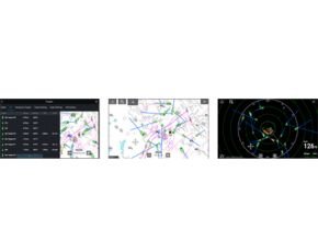
The AIS700 from Raymarine is a Class B Automatic Identification System (AIS) transceiver designed for use with Raymarine multifunction navigation display systems. As a Class B AIS transceiver, the AIS700 not only receives broadcasts from other vessels, it also transmits your own boat’s information too helping you to be seen on other vessels’ systems.
AIS700 FEATURES

- Full transmit and receive AIS for enhanced situational awareness and safety.
- Latest SO-TDMA networking for longer range and faster performance.
- Built-in antenna splitter simplifies installation with existing VHF radio antenna.
- NMEA2000, NMEA0183, PC (setup & diagnostics) and SeaTalkng compatible.
- Software or hardware switchable Silent Mode for enhanced security when needed.
AIS700 SPECIFICATIONS
| TECHNICAL SPECIFICATIONS |
ENVIRONMENTAL SPECIFICATIONS
| Operating temperature | -15°C to +55°C |
| Storage temperature | -20°C to +75°C |
| Water ingress | IPX6 and IPX7 |
| Humidity | Up to 93% @ 40°C |
POWER SPECIFICATIONS
| Power Supply | 12v and 24 nominal |
| Power Consumption | <3W |
| Peak current | 3A |
| Load Equivalency Number | 1 LEN |
RF SPECIFICATIONS
| DSC Receiver | Implemented by time sharing with one TDMA receiver |
| Receiver 1 band | 156.025 MHz to 162.025 MHz (in 25KHz steps) |
| Receiver 2 band | 156.025 MHz to 162.025 MHz (in 25KHz steps) |
| Transmitter band | 156.025 MHz to 162.025 MHz (in 25KHz steps) |
| Transmitter specification | To meet IEC 62287-2 relevant sections |
| Receiver specification | To meet IEC 62287-2 relevant sections |
| Transceiver specification | To meet IEC 62287-2 relevant sections |
| GPS receiver | u-blox MAX-M8W |
| GPS receiver channels | 72 channels |
| GPS Cold start acquisition time | 26s nominal |
| Positional source | GPS & GLONASS |
| AIS performance | 5W SOTDMA |
ANTENNA SPLITTER SPECIFICATIONS
| Operating frequency range | 156.0MHz to 162.025MHz Transmitting 156.0MHz to 162.025MHz Receiving |
| Insertion loss AIS RX path | 0dB |
| Insertion loss AIS TX path | <1dB |
| Insertion loss VHF RX path | 0dB |
| Insertion loss VHF TX path | <1dB |
| Power handling AIS port | Maximum 5W input |
| Power handling VHF port | 25W input |
| Switching time RX to VHF TX | 10uS Max |
| Switching time RX to AIS TX | 10uS Max |
| Switching time VHF TX to AIS TX | 10uS Max |
| Switching time any TX to RX | 10uS Max |
| VHF port impedance | 50 Ohms |
| AIS port impedance | 50 Ohms |
| Antenna port impedance | 50 Ohms |
| VHF to AIS port isolation | >28dB (both directions) |
| Minimum VHF input power for switching | 400mW |
*To share a VHF antenna, the aerial should meet the following requirements (nominally tuned to 159MHz):
| Frequency Band | 156.025 MHz to 162.025 MHz |
| VSWR (Voltage Standing Wave Radio) | Should not exceed 2:1 |
| Impedance | 50 Ohm |
| Gain | 3dBi Max |
| Connector | PL-259 |
EXTERNAL CONNECTIONS
| VHF antenna connector type | SO-239 co-axial |
| VHF radio connector type | SO-239 co-axial |
| GNSS antenna connector | 50? TNC co-axial |
| NMEA2000 | DeviceNet male |
| USB | Micro-B |
| External interface isolation | NMEA0183 and NMEA 2000 interfaces to incorporate galvanic isolation from power supply as required by the relevant interface specification. |
| NMEA0183 interface 1 (MFD connection) | NMEA 0183 HS (IEC 61162-1) compliant, bi-directional, RS422 levels. 4 wire interface (differential signalling). Configurable baud rate. Input to MFD from AIS. |
| NMEA0183 interface 2 (NMEA0183 instrument connection) | NMEA 0183 (IEC 61162-1) compliant, bi-directional, RS422 levels. 4 wire interface (differential signalling). 4 wire interface (differential signalling) Configurable baud rate |
| USB interface (PC connection) | Protocol NMEA 0183 HS (IEC 61162-1) compliant, bi-directional USB port, 38.4 kBaud |
AIS700 ORDERING INFORMATION
| ORDERING INFORMATION | |
| Part Number | Description |
| E70476 | AIS700 Class B Transceiver with integrated antenna splitter |
AIS700 WHAT’S IN THE BOX
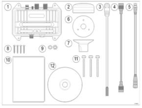
| IN THE BOX | |||
| 1 | AIS700 Class B AIS Transceiver with built-in VHF antenna splitter | ||
| 2 | GNSS (GPS) Antenna with captive cable 10m (33 ft) | ||
| 3 | Power / data cable 2m (6.56 ft) | ||
| 4 | VHF Radio cable 1m (3.28 ft) | ||
| 5 | DeviceNet to SeaTalkng® adaptor cable 1m (3.28 ft) | ||
| 6 | GNSS antenna gasket | ||
| 7 | GNSS antenna pole mount | ||
| 8 | Unit fixings (4 x No.8×19 self tapping screws) | ||
| 9 | M5 nut and washer (grounding) | ||
| 10 | Documentation kit | ||
| 11 | GNSS antenna fixings (3 x M3x40 stud and thumb nut) | ||
| 12 | Software CD | ||
Read more :