SC Hydraulic Engineering 10-6 & D6 Liquid Pump
SC Hydraulic Engineering 10-6 & D6 Liquid Pump is a leading manufacturer and designer of an ever-growing line of high-pressure, air-driven liquid pumps, as well as air and gas boosters which are being used in a variety of industries and applications.
Growing since 1953, we continually develop new hydraulic and pneumatic equipment to meet the constant stream of newly emerging applications. We offer liquid pressures as high as 65,000 psig and can exceed 17,000 psig in gas pressures.
General Product Information
- HIGH OUTPUT CAPACITY
- GUARANTEED PERFORMANCE
- MULTIPLE OUTPUT CAPACITIES
- SIMPLE OPERATION PRINCIPLE
- DESIGNED FOR EASY MAINTENANCE
- WIDE RANGE OF OPERATING PRESSURES
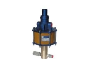
10-6 & D6 Series pumps have a 7″ diameter air piston and a 2 1/2″ stroke. Thirteen models are available with pressures up to 65,000 psig.
When operating from 0 to rated hydraulic pressure, air consumption will be approximately 56 scfm of free air at 100 psi output. At lower air pressures and higher hydraulic pressures air consumption will be reduced proportionately to flow rates indicated.
Mounting may be in any position, vertical preferred. When mounted in an inverted position, a drain cock should be provided to drain off any liquid that may accumulate in the pilot valve air chamber.
The D6 Series “Dry Lube” pump is identical to the 10-6 Series except it is pre-lubricated and therefore does not require an air line lubricator. The part number distinguishes it from the 10-6 Series by the D6 prefix and using the actual ratio rather than a numerical code in the model suffix.
Application
- Staking
- Piercing
- Blanking
- Pressing
- Clamping
- Metal forming
- Static and burst testing
- Hydraulic Press operation
- Flow testing requiring relatively low flows at high pressures
- Applications requiring extreme intermittent pressure and velocity are commonly associated with water blasting and jetting.
| Model No. | Maximum Material Rated Gas Supply Pressure (Ps) | Maximum Material Rated Gas Outlet Pressure (Po) | A Inlet Port B Outlet Port | Static Outlet Stall Pressure | Minimum Inlet Gas Pressure (Ps) | Displacement Per Stroke (in3 per cycle) |
| GB-D30 | 6 | 9 | 1/4″ NPT | 60 Pa | 200 psig (13 bar) | 3.1 |
| 410 bar | 620 bar | 1/4″ NPT | ||||
| GB-D75 | 6 | 20,000 psig | 9/16″-18 (1) | 150 Pa | 250 psig (17 bar) | 1.2 |
(1) Coned and threaded high-pressure connection for 1/4″ O.D. tubing.
(2) Maximum allowed working pressure for oxygen service boosters: 5,000 psi max.
(3) Maximum allowed working pressure for hydrogen service boosters: 6,000 psi max.
(4) Oxygen & hydrogen service boosters are not available on all models. Contact the factory for more information.
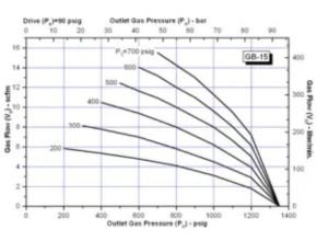
Refer to corresponding gas booster performance curve for operating pressures. Maximum material-rated outlet pressures can be reached under special operating conditions. Do not use air drive and/or gas supply pressures that equate to higher outlet pressures than those “maximum material rated outlet pressures” shown on table. Refer to Static Outlet Stall Pressure formula shown on table (for example, for gas booster model GBD-30 the formula is: Static Outlet Stall Pressure = 30*Pa+Ps). Maximum recommended air drive operating pressure: 100-psi. Maximum rated air drive pressure: 150 psi (only for static outlet stall pressure).
Ordering
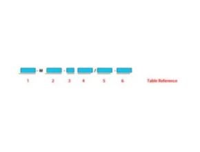
| TABLE 1 | Gas Booster Series (1) | ||
| GB | Single Stage | ||
| TABLE 2 | Modification | ||
| Blank | No Modification | ||
| M402 | Remote Pilot | ||
| 3 | EPR O-rings, Polyurethane Main Seal | ||
| TABLE 3 | Cylinder Modification | ||
| Blank | Single Head | ||
| TABLE 4 | Pressure Ratio Single or First Stage | ||
| 5 | GB | ||
| 15 | GB | ||
| 30 | GB | ||
| 75 | GB | ||
| TABLE 5 | Pressure Ratio Second Stage | ||
| Blank | N/A on GB Series | ||
| TABLE 6 | Service Option | ||
| Blank | Standard | ||
| 2 | Oxygen Service (2) | ||
| H2 | Hydrogen Service (2) | ||
| Notes : | (1) Do not fill gap on a two digit description | ||
| (2) Not available on GBD-D75, GBT-D15/75 and GBT-D30/75 models. Contact factory for more information. | |||
Performance Chart
Modification
A Models: These models utilize dual seals in the hydraulic assembly with a bleed-off between the seals to the atmosphere, thus providing a visual indication of hydraulic seal leakage. Used where contamination of the air motor from the hydraulic fluid being pumped is objectionable.
B Models: The “B” models have a bottom inlet connection for convenient tank top installation or alternate mounting configuration.
C Models: The “C” Models utilize PTFE chevron packing in the hydraulic assembly for ultimate performance when another packing material is not compatible with the fluid used or because of extreme temperature conditions. The “A” modification is included on all “C” models and the check valves have PTFE o-rings.
H Models: The “H” Models utilize special packing in the hydraulic assembly for maximum performance where hydraulic fluid media is contaminated with foreign matter, thus providing for a much greater life expectancy from the hydraulic seals than with standard o-ring seals. The “A” modification is included on all “H” models and the check valves have PTFE o-rings.
K Models: These models utilize a special air piston in the air motor assembly which decreases the stroke of the pump, thus minimizing the internal forces and increasing air motor life. Used in applications exhibiting rapid pressure losses, such as burst testing.
R Models: The “R” Models are furnished with an isolator attachment that prevents the hydraulic piston from retracting into the air motor during operation, thus providing for 100% non-contamination of the hydraulic assembly from the air motor. The isolator also acts as a heat barrier.
Read More Articles:
- SC Hydraulic Engineering GB Series Gas Booster Single Stage
- SC Hydraulic Engineering GBD Series Gas Booster Single Stage Double Acting
- MPV LED MARINE SIGNALS
- Sealite Mooring Buoys SL-MB 650mm
- Electro-hydraulic Actuators for ship
Source: schydraulic.com