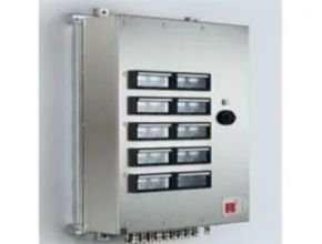
R. STAHL Series 8150 Control For Marine Application
R. STAHL Series 8150 control and distribution boxes are made of brushed stainless steel (1.4301, AISI 304 or 1.4404, AISI 316L) and are particularly robust: The high-quality sealing materials make them suitable for an extended temperature range and a circumferential protection channel prevents ingress of water. A flange plate facilitates assembly.
- Ex e terminal boxes made of stainless steel that can be individually equipped
- The cover is either equipped with a hinge (large opening angle, 130°) and cam lock or with a screw-on cover
- Numerous standard sizes in stock
| Product Description : | Control box |
| Product Type : | 8150/5-0360-0176-091-3311 |
| Art. No. : | 206554 |
| WebCode : | 8150B |
| Availability | Available in the short term |
- Ex e terminal boxes made of stainless steel that can be individually equipped
- The cover is either equipped with a hinge (large opening angle, 130°) and cam lock or with a screw-on cover
- Numerous standard sizes in stock
TECHNICAL DATA
GENERAL
| WebCode | 8150B |
| Product Type | 8150/5-0360-0176-091-3311 |
| Product Description | Control box |
| Highlights | Ex e terminal boxes made of stainless steel that can be individually equipped The cover is either equipped with a hinge (large opening angle, 130°) and cam lock or with a screw-on cover Numerous standard sizes in stock |
| Functional Description | R. STAHL Series 8150 control and distribution boxes are made of brushed stainless steel (1.4301, AISI 304 or 1.4404, AISI 316L) and are particularly robust: The high-quality sealing materials make them suitable for an extended temperature range and a circumferential protection channel prevents ingress of water. A flange plate facilitates assembly. |
EXPLOSION PROTECTION
| Application range (zones) | 1, 2, 21, 22 |
| IECEX gas certificate | IECEx PTB 09.0049 |
| IECEx gas explosion protection | Ex eb IIC T6/T5/T4 Gb |
| IECEX dust certificate | IECEx PTB 09.0049 |
| IECEx dust explosion protection | Ex tb IIIC T80 °C … T95 °C … T130 °C Db |
| ATEX gas certificate | PTB 09 ATEX 1109 |
| ATEX gas explosion protection | II 2 G Ex eb IIC T6/T5/T4 Gb |
| ATEX dust certificate | PTB 09 ATEX 1109 |
| ATEX dust explosion protection | II 2 D Ex tb IIIC T80 °C … T95 °C … T130 °C Db |
| Ship approval | DNVGL |
ELECTRICAL DATA
| DC rated operational voltage | 1000.00 V |
| Rated operational voltage AC | 1000.00 V |
| Rated operational voltage DC | 0.00 – 1000.00 V |
| AC UL rated operational voltage | 600.00 – 600.00 V |
| Rated operational current | 630 A (T6) |
| UL rated operational current | 10.000 A |
| Frequency range | 50 – 60 Hz |
AMBIENT CONDITIONS
| CAN UL ambient temperature °C | -60 – 40 °C |
| USA UL ambient temperature °C | -60 – 40 °C |
| USA UL ambient temperature °C 2 | -60 – 55 °C |
| CAN UL ambient temperature °C 2 | -60 – 55 °C |
| USA UL ambient temperature °C 3 | -60 – 70 °C |
| CAN UL ambient temperature °C 3 | -60 – 70 °C |
| Ambient temperature | -60 °C … +40 °C (IIC T6) (T80 °C) -60 °C … +55 °C ( T5) (T95 °C) -60 °C … +70 °C (T4) (T130 °C) |
MECHANICAL DATA
| Degree of protection (IP) | IP66 |
| Enclosure material | Stainless steel 1.4404, (AISI 316L), brush finished |
| Silicone-free | No |
| Wall thickness | 1.50 mm |
| Cover thickness | 2.00 mm |
| Fixing dimension a1 | 320 mm |
| Fixing dimension a2 | 136 mm |
| Fixing dimension b1 | 396 mm |
| Fixing dimension b2 | 212 mm |
| Fixing dimension c1 | 412 mm |
| Fixing dimension c2 | 228 mm |
| Total depth H | 106 mm |
| Width | 360.000 mm |
| Height | 176.500 mm |
| Depth | 91.000 mm |
| Weight | 0 lb |
A vessel was in port and the crew was loading logs on to the hatch covers. The securing system involved the use of foot wires, snatch blocks, and a wiggle wire (see image). Although it was dark, the deck was well lit by the ship’s own floodlights and the floodlights on the wharf.
The crew was wearing personal protective equipment (PPE), which included boot spikes to reduce the risk of slipping on the wet logs. The number one crane was being used to tension the wiggle wire, and two deck crew were standing close by to check the tension in the wire. The bosun was communicating with the crane operator using hand signals.
Tension was brought on the wiggle wire and then stopped at a signal from the bosun. The bosun started to walk towards the two-deck crew in preparation to attach bulldog grips to secure the tensioned wire when a foot wire directly in front of the two-deck crew suddenly parted.
The rapid release of tension allowed a block and the wiggle wire to recoil towards the two-deck crew. Both crews were struck by securing equipment and/or wire; one sustained minor injuries but the other later died of his injuries.
The investigation found that the member of the deck crew, whose role was to monitor the tension, had no way of determining how much tension was in the wire other than by feel, which was done by depressing the wiggle wire with their foot. This improvised procedure led them to stand in a hazardous area close to a wire under tension. As it was, the investigation found that the foot wire parted as a result of over-tension.
According to the vessel’s cargo securing manual, only a nominal initial tension was to be applied to the wiggle wire since turnbuckles were supposed to be rigged between the wiggle wire and foot wires (see diagram in next column), to permit manual re-tensioning when needed. In this case, the crew member had decided not to use turnbuckles but to try to tension the wire fully with the crane.
Read More Articles :
- JUNCTION BOXES SERIES 8102
- M860 Solar Powered LED Marine Lantern from 4 to 7+ NM Range
- STAHL FLoodlight LED Series 6125/2 For Marine Application
- MPV LED MARINE SIGNALS
- 3-5 NM Solar Marine Lanterns
Sources : r-stahl.com