Ship Windlass Maintenance Procedure
Most of the windlasses found onboard ships these days are driven directly by electric motors or by pressurised hydraulic oil.
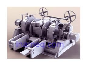
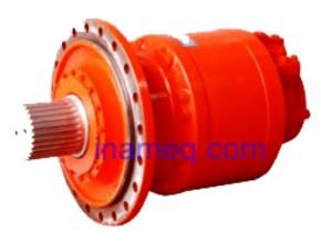
They cater to hoisting up varying loads with the help of gear and teeth arrangement. The major parts of a windlass are main shaft, driving shaft, inspection cover, gear, gear frame, drums (one or more), warping head or couplings, brake band, brake liner assembly, chain wheel, gear wheel, pinion, clutch and high speed low speed hydraulic valve blocks.
Regular inspection of external and moving parts of gear and shaft enables a ship’s officer to judge the wear and amount of use of this important machinery.
While using windlass for hoisting, an early indication can be temperature rise on the exterior of hydraulic pipe lines driving the main shaft. This further needs to be investigated for the correct technical specification and properties of the oil used and load on the motors and working pressure of the driving hydraulic oil. The bearing, pin and sliding parts of the assembly require a special grease recommended to be used on open gears to prevent them from weather damage as well. Often the maintenance routines for the filters of the hydraulic pumps used for running windlasses are followed by ship’s staff. The oil samples are also collected periodically for analysis.
The main shaft or gear shaft too may be checked for temperature rise to indicate lack of or less lubrication than required. The main shaft extends outside the gear frame and is equipped with drums, warping heads or cable lifter unit. The shaft consists of shaft and pinion and shaft roller bearing, which is lubricated through the grease nipple.
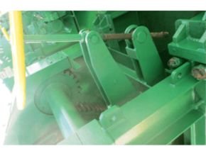
The drums are usually provided with manual brakes or they can be hydraulic operated brakes. Brakes are provided with foundation plate welded to the deck.
Often windlass shaft is coupled with mooring winch and it is important to put the mooring winch brake ‘on’ and the clutch in disengage position for the winch before operating the windlass.
When anchoring speed is high the anchor runs away and the brake lining might get damaged due to heat. Thus dropping the anchor and repeating the drop and stoppage at every ½ shackle is advisable to prevent damages to brake liner due to temperature rise.
In rough weather it is necessary to loosen the anchor chain tension while heaving up by using engines to avoid excessive load on the windlass. In case excessive load is applied on the windlass while heaving, bring the operating lever to neutral position then pay out the cable little bit, increase engine revolutions and heave the chain again once the load reduces. Speed change for windlass from high to low will cause large speed change and thus they are constructed with utmost safety features.
A weekly schedule for windlass should involve lubricating all the plain bearings through the grease nipples and the gear teeth. Monthly or quarterly checks recommended for the condition of brake linings should be carried out depending on the frequency of use. Monthly routines should include all the couplings, hydraulic valves and piping to be checked for leaks, tightness and functioning. Covering couplings with anti corrosive tapes can prevent them from getting rusted. The hydraulic motor foundation to be checked for tightness and any sign of wear at the base.
On an yearly basis the bearing clearances, gear wheel contact areas and hydraulic valves to be adjusted for correct operating pressure. The bolts and nuts should be checked for proper tightness. The gear contact should be at least 70% or more failing which the gear wheel gives abnormal noise. Preventive actions can be greasing of gear teeth or the realignment of windlass.
Adjustment of brake settings of windlass : When the brake lining has worn away it can be adjusted to render the necessary holding force. Often manufacturer’s recommend after a specific reduction in thickness of the brake lining to replace it with new one. However, when the liner thickness reduces within the limits applicable, brake setting can be adjusted with the regulating screw as a makeshift measure. Both the linings, upper and lower should be changed at the same time.
During liner replacement it is very important to secure the chain and anchor with extra lashings if the ship’s staff is carrying out this job at sea. The job should preferably be carried out in calm waters without any uneven rolling or pitching. When the anchor and chain is secured by the stopper and extra lashings the brake assembly can be checked. For that the brake has to be fully opened and all the pins connecting to the brake has to move smoothly, cleaning, greasing or hammering of pins may be required for this purpose. The brake nut can be used to adjust the length of brake spindle which in turn corresponds to the liner thickness.
It is very important that while replacing the brake liner assembly of a windlass the position of the brake screw down lever and position of brake bands corresponding to the brake position is marked. As after replacing the liner misalignments are often observed while reassembling the whole unit.
The spherical roller bearings assembled to the main shaft are precision built and care must be taken while removing them. If any roller bearings fail it should be completely replaced. Never strike a roller bearing with a steel hammer. A wood hammer or soft hammer should be used to strike it lightly.
Read more : Planning and operational guidance for anchor ship
Hydraulic Windlass
The hydraulically operated windlass has larger torque capacities because the hydraulic motor can operate at very low speeds even at 5 to 10 rpm, there by building a very high torque. The torque –speed characteristics of hydraulic system is much better and flexible than electrical systems. Their comparison is shown in the sketch given under.
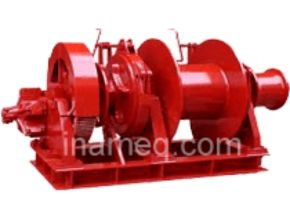
The Hydraulic machine is robust and can withstand a lot of shock. The components are less since the double reduction gear box and the slip clutch are eliminated thereby reducing the cost of the machinery. For safety a spring loaded shock valve is provided in the system which will connect the high pressure to the low pressure side when overload occurs. The hydraulic windlass cum mooring winch is illustrated below.
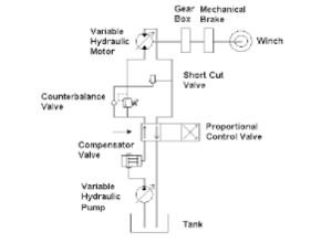
Hydraulic System
The hydraulic system schematic sketch below is illustrated as The main components of this system consists of the following :
- An expansion tank located on the forecastle deck to give a good head to the oil to flow.
- The gear pump located in the forecastle.
- The oil storage tank located in the fore castle store with attached hand pump to transfer oil to the expansion tank.
- The hydraulic motor mounted on the windlass frame and connected to the primary driving The control block is integral with the motor casing and cut sectional sketch of the motor is illustrated separately.
When the control block is placed in the neutral position the oil flow to the motor is prevented by the blanked connection in the block in this position. When the block is shifted to no 1 position only two paths are connected and the flow quantity being moderate it gives the rated speed and torque. When it is shifted to the 2nd position the oil flow has 4 paths and this conforms to the higher torque and speed rating. This position is used for breaking the anchor hold in the ground and when free the block can be used for lifting the anchor along with chain When the block is shifted to the upper R position the passages in the block are crossed causing the flow of oil in reverse direction thereby turning the motor in the reverse direction.
For mooring winch operations no 1 and R positions are used as convenient. For normal anchor lifting no 1 position is used. For walking back the anchor R position is used. For breaking anchor from ground no 2 position is used.
When changing over from 1 to 2 more oil is required and this is provided by oil flow from expansion tank to pump through a non return valve. When changing over from 2 to 1 excess oil from system flows back into expansion tank by another non- return valve.
Hydraulic motor
The motor is simple in construction at the same time it is robust and can take a lot of rough handling. The rotor is a thick disc with rectangular slots cut on the circumference. Each slot accommodating a thick vane held in place by the cover plate. The vanes are made to press hard on the casing (internal) surface by a bow spring held under the vane.
The rotor is mounted on a strong roller bearing and also carries an oil seal which prevents leakage of oil during operation.
Maintenance
During lay ups at special surveys, the end cover is opened up and vanes as well as springs which are damaged are renewed. The oil seal and roller bearing also renewed if they are worn out. The sketch of the winch motor with detail of vane assembly is shown under.
The electric motor driving the gear pump is a three phase double squirrel cage motor with high slip capability combined with higher rotor current capacity because of the two layers (radially) of copper bars embedded in the iron rotor. The sketch of this rotor is reproduced as under.
Read more :